 Ron's Range Rover 38A HSE Mods.
Return to Ron's Rover Home Page
 Ron's Range Rover 38A HSE Mods.
Return to Ron's Rover Home Page
Dual battery setups seem to be rare in this model Rangie. As mine is a GEMS EFI system (not the later Thor aka Bosch), it has the engine management system behind the exisiting battery so that takes up some room that could have been used for a second battery. I've seen one installation nwhere the owner had fitted two expensive Optima batteries in place of the original single but that was out side my budget. My car is RHD so there is no space behind the coolant reservoir as that space is taken by the ABS braking system. It may be possible to fit a second battery there on LHD cars - i don't know as I haven't seen any pics of that area.
I opted for fitting the second battery in the wheel well. I have a 100 Ah AGM (Absorbed Glass Mat) battery which is spill proof and can be used in any position.
These were photos taken before the snorkel and LPG system were fitted.
A couple of areas of concern with this early arrangement were (a) water flowing up into the air cleaner horn during a water crossing and (b) what would happen with an engine backfire if the battery was gassing off. I believe the snorkel arrangement overcomes both problems.Above right: (20Kb) Note from the picture that the air cleaner trumpet sits right over the top of the battery. I had to make up a new support bracket to lift the aircleaner and move it backwards. The bent rubber duct originally connecting the air cleaner to the air flow meter (not used with my Haltech EFI computer) was replaced by a piece of 80mm diameter reinforced rubber hose. Note that these changes may not have been necessary had I had fitted the snorkel before the second battery. In fact, fitting the snorkel may have allowed me to revert to the earlier aircleaner fittings.
Also note that the power steering fluid reservoir bottle (between the radiator hose and the intake trumpet) was relocated and attached to the top left radiator support bracket (also modified and strengthened). The bottle bracket was straightened to allow it to be bolted to the radiator support bracket.
The battery controller is the Electronic Australia Smart Dual 12v Battery Controller design published in the January and February 1996 issues.
 Left: (12Kb) In an accident, a hi-lift jack isn't
the sort of thing you want floating around inside the Rangie. The following
idea isn't mine. I copied it from my ex-brother-in-law's Nissan Patrol setup.
It only went on for 4WD trips so it didn't normally intimidate pedestrians.
I sometimes carried the hi-lift behind the rear seat with the axe, bow saw, and tyre beadbreaker when I had my storage box frame and cargo barrier fitted.
Right: (18Kb) Notice how the hi-lift was bolted to the brackets on the
bull bar. 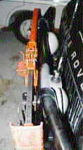
Below (7Kb) is the bracket. It was made from 1/4" (6mm) plate steel with four mounting holes which were used to bolt it to the bull bar. The support rod was actually a 1/2" UNF bolt. I cut the bolt head off and cut a new thread at the end. This new cut thread was screwed into the central hole in the plate and the bolt then welded into place. For the bolt to come out, the welds would have to fracture, then the bolt would have to unscrew.
The outer end of the bolt (the long threaded section) was cross-drilled for a retaining clip. Two of these assemblies were bolted to the bull bar, when required, using the four outer holes.
The hi-lift was slid over the bolts and bolted on and then retaining clips fitted so even if the nyloc nuts came loose, the hi-lift could not come off. It also slowed down any would-be thief. In the bush, the nuts could be removed and the hi-lift retained by the clips. To stop rattles in this situation, I had two pieces of 10mm thick rubber are placed behind the jack and which took up the slack left when the nuts were removed.
Left: (8Kb) This photo shows how I aligned it onto the bullbar before drilling the mounting holes. The left plate was held in place with vice grips (mole grips) and the jack slid on. The right hand plate was then fitted to the jack and then clamped to the bull bar. Slight adjustments were necessary to align the plates on the uprights. Note: you must do this to ensure that the holes in the jack post fit over the pegs in the plates. If you just bolt the plates up, there is every likelihood that you won't be able to get the jack on.
 Left: (10Kb) This shows the final installation of the Haltech EFI computer
on the right hand kick panel between the door and the remote bonnet release
handle. The grey plastic kick panel cover had been trimmed to go around the
ECU box which was screwed to the kick panel.
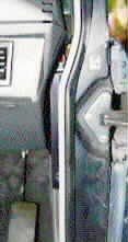
Right: (16Kb) This view is looking at the gap between the door pillar and the lower fascia panel under the dash. Note how the EFI computer (the slim black bit) has been slid up into that gap.
Left: (12Kb) Similar view to that above but this time without the lower fascia in place. To fit the ECU here meant knocking down a flange on the kick panel. Don't forget this is a RHD vehicle so it's probably back to front for LHD vehicles. That black rubber tube is a vacuum line for the MAP (manifold absolute pressure) sensor. The bottom edge of the ECU is level with the bonnet release handle. It gave me 12 inches (300mm) more freeboard! I originally planned to seal the case with silicone rubber but experience with sealing radio control systems for model boats makes me know better. The acetic acid released by many silicone rubbers promotes corrosion of the electronics.
 Right: (6Kb)
To be able to slide the EFI computer
up into that gap required a slight trimming of the edge of the lower fascia. Here
it can be seen how I trimmed the side (the lower edge in the photo). To visualise
this, turn the picture 90º anti-clockwise. Note this is for a RHD vehicle.
This lower fascia is reinstalled after the ECU is fitted.
Right: (21Kb) View from the top and left of the carrier. Note the chain inside the bicycle tube. The tube is to prevent sparks from the steel chain clunking against the steel can near their lids. The number plate lights (yes, from a Toyota FJ40 - it was free) plug into the trailer lighting socket under the ARB step bar. The small brackets at the outer ends of the carrier and which sit on top of the step bar are to stop the carrier rocking from side to side. These brackets have thick rubber underneath. The carrier was surprisingly stable and didn't rattle even on rough roads.
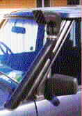 Right: (15Kb) Whilst the majority of serious (and some not so serious) 4WDs in Australia have commercially available snorkels, until recently these were not available for the Range Rover. Now that they are, the ones I've seen are pretty ugly fibreglass mouldings - and all snorkels, regardless of the 4WD to which they are to be fitted, are expensive. So why not make one's own? This one is merely 75mm (3") steel exhaust pipe, bent to shape. The ram on the top is the Safari Snorkels ram (possibly made by Donaldson, the US filter company - it looks like theirs).
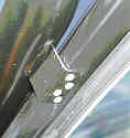 Left:
(10Kb) The right-angled bracket by which it is attached to the windscreen pillar is a piece of 50mm (2") x 2mm thick square steel tubing which was sliced diagonally to give two angled brackets, only one of which was used. It is welded to the round pipe and pop-rivetted to the screen pillar. I temporarily fitted the snorkel in position before making the bracket. To get the position exactly aligned, I marked the bracket in-situ, trimmed it to size and then superglued it in place. I reinforced the superglue with baking powder but you could use micro-balloons (both are common techniques for aeromodellers). I then carefully removed the snorkel so as not to break the superglued joint. Finally, I welded the bracket on. The superglue and baking powder soon burned off. The image above right (9Kb) shows the shape of the steel tubing.
 Right:
(15Kb) The air cleaner was modified by the removal of the horn. A trimmed down 75mm rainwater downpipe fitting was brazed on in its place. The flexible hose is 75mm Calor ducting I bought from Pirtek (the specialist hose company). It isn't cheap at A$40 per metre!
One problem with the boat bilge blower ducting I originally used is that because it was so thin, the first time I went for a drive, the excess ducting got sucked into the aircleaner and the engine wouldn't run! This Calor stuff is better and is rated for temperatures from -25ºC to 125ºC.
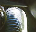
 Left: (8Kb) 75mm pipe won't fit through the bonnet (hood) closing faces unless the bonnet and the decker panel are opened up. These pix show how much metal has to be filed away. It looks worse than it is because the bonnet had to be lifted a bit for me to take the photo.
Right: (15Kb) The bonnet light switch mounting hole also needs opening up to allow it to be moved slightly up and out to clear the snorkel . Alternatively, you could relocate this switch across to the RHS of the bonnet. I couldn't do this because that position was taken by the burglar alarm switch.
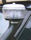 Left:
(12Kb) A couple
of trips away had seen me and my Rangie in the position of Tail-End Charlie and,
consequently, travelling in a billowing dust cloud. The effect on the Finer
Filter oiled foam air filter was quite marked. As a result, I bought a Donaldson
pre-cleaner to replace the ram at the top of the snorkel. The pre-filter was cheaper
than the ram but it doesn't look as "pretty" in the city. One advantage of the
pre-filter is that the oiled air filter doesn't get coated in flies, moths and
bugs as they are trapped in the pre-filter - you can watch them being spun around
by the air flow in the dust collector bowl.


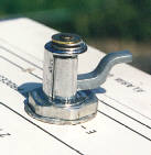 Left: (15Kb/19Kb) The early Rangies have open seat bases with nothing under them except the ECU (which has been relocated on my car). So they are useful for storage. But who wants it all showing?
So I made up some aluminium cover plates which are held in position by clamping nuts - see pix (right) - "rescued" from some old electronic equipment being dumped from where I worked. When the black knob on the outside is turned, this item on the inside rotates 90 degrees and then screws up to clamp the front panel in place. It is actually in the screwed up position as shown.
 Right: (29Kb) What's special about this? Nothing. It is here the show the fairing that the previous owner of the rack had fitted. It looks somewhat ugly but it keeps the noise level down. I later took the brown paint off it. Note the air pre-cleaner on the snorkel.
 Right: (25Kb) The Rover diff is well known for the very thin steel cover over the crown wheel and for the fact that the crown wheel is so close to the cover. A slight hit on the cover will see the crown wheel chew a hole through the cover in short order. The oil then tends to come out! This diff guard is one photographed on another Rangie, that's why it is slightly different in appearance.

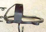
This diff guard was purchased from John E. Davis Motorworks (JDM) in Sydney, Australia. JDM were a significant force in Land Rover mods etc. in Australia. They made the Bush Rangie shown on the main Rover page of this web site. They have now been replaced by Bruce Davis Performance Landys. Bruce is John's brother.

 Left & Right: (25Kb each) The Range Rover has a fuel capacity of only 80 litres - far less than the typical large Japanese 4WD and, combined with the thirst of the V8, range is somewhat limited at about 400km - so I fitted an aftermarket auxiliary fuel tank of 40 litres capacity under the left hand sill.
Sill tanks are not feasible on EAS model Range Rovers because that's where the EAS compressor and control valves are located. The sill tank has the advantage of better distributing the weight - not all the increased weight hangs under the rear of the vehicle. 
The tank is filled from under the left rear mudguard (fender - US, wing - Britain). Some sill tanks fill through the floor in front of the front seats. I wasn't keen on that idea.
 Right: (25Kb) Converting the Range Rover to LPG afforded a significant reduction in operating costs. I drove the Rangie to work every day (120km a day) so I racked up a fair few kilometres over a year. The cost of conversion was A$1,800. In Australia, this work has to be done professionally and the vehicle has to have a compliance plate fitted. Unlike Britain, there's none of the DIY stuff here.
The tank is a 70 litre (56 litres usable) mounted fore and aft on the right hand side of the cargo bay. I wanted it this way so that the cargo bay cover could be retained and so that I still had a flat floor when the rear seat is laid down. The disadvantage is the relatively small tank capacity.
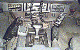 Right: (25Kb) The Range Rover is somewhat bereft of places to fit CBs. In Australia, one really needs two radios, one on 27MHz AM and the other on the 477MHz UHF FM band. (Recently Uniden have released a radio that combines both into one compact unit.) The FM sets provide a lot of advantages apart from clearer reception, some have selcall, scanning (open and closed group), etc. But where to fit them?
I could have purchased a ready made radio console from The Dept of the Car Interior. They make the consoles. But I'm cheap - so I mounted the UHF radio (a GME Electrophone TX4000) on the left side of the transmission tunnel console and the 27MHz set on the right hand side of the car radio panel. See pix (I should have cleaned the Rangie first).
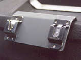
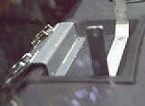

Putting the microphones somewhere is difficult so I made up this bracket which is screwed to the existing holes in the tray on top of the dash. No holes need to be drilled in the dashboard. (I tried double sided tape but the mike clips kept falling off in the sun). The bracket in the background is to hold the very old GPS display I had at the time.
The shape of the bracket is shown in the pix on the left. I painted it to match the dash after taking the pictures. As you can see it's approx 2 mm aluminium with some simple folds (I have a mini panbrake for doing this sort of work).

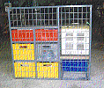 Left and right: (35Kb and 50Kb) I didn't want everything in the back floating around as I bounced around in the bush - or coming into the front of the cabin, so I made up this storage unit for my stuff when I went camping. It holds the Engel 29 litre fridge, 1 x 26 litre drawer, 8 x 15 litre drawers and 4 x 6 litre drawers. I built in a cargo barrier as well - see pix (right). The frame is made from 20mm square steel tubing welded together. The drawers shown here upside down have a lip at the bottom and just drop into place so they can't slide out. There is enough clearance at the top of the drawer to allow the drawer to be lifted clear and slid out. Click here to see how the bottom of the drawer slides between the square steel tube runners (also note the mesh between the drawers so that if a drawer does bounce out of the runners, it can't move sideways into the adjoining drawers - if that makes sense).

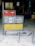 Left and right: (42Kb each) I wanted to leave the spare wheel in its original location so I made the fridge support removable. I figured that if I had a flat tyre in the bush, I was going to take the time to have a cup of tea so the extra time to remove the fridge would be insignificant. To locate the sub-frame, I welded square steel tube sockets to the main frame into which the sub-frame fits. It is effectively locked into place by virtue of the fridge hold down straps (not shown in these pix).
The Range Rover didn't have any tie down points in the rear so I made those up as well. When the rack is fitted, it is bolted into position. It won't move.

Because the Rangie has an aluminium floor in the rear compartment, just bolting through it didn't seem safe to me. I wanted strong mounting points in the event of an accident. The front mounts are attached to a steel channel that is bolted to the chassis (see right), not the floor. I removed this channel and welded two nuts to it. I used Hillman wheel (lug) nuts because I had them and they fitted the bolts I had - which just happened to be some left over seat belt mounting bolts. I like these because they are high tensile steel.

The rearmost mounts are again Hillman wheel nuts but this time they are welded to a large flat piece of steel which was pop-riveted to the alloy floor. The large area was required to distribute the load so the nut wouldn't pull through the floor.

The Range Rover rear floor is corrugated so I needed some spacers to fit into the corrugations so that when I was using tie downs and not the rack, the tie downs would sit above the rubber mats. So I machined 4 alloy spacers up in my lathe. When I'm using these points as tie downs, I bolt some metal pieces from seat belt anchorages into place. These are the anchorage points from the door pillars on Hillmans through which the seat belt webbing runs. The tie down straps are threaded through the slots in the attachments. I punched the holes in the rubber mat using a large wad punch.
 Left: (23Kb)
In 1997, My wife was a little
surprised when I took these photos (large image is different view) to the hospital
to show her how her Rangie was being treated whilst she was laid up. I wonder
why? It was a good opportunity to do some work on it and it was soon back together
and operational.
Email Ron Beckett with comments about this site
This page was last updated 25th June 2007